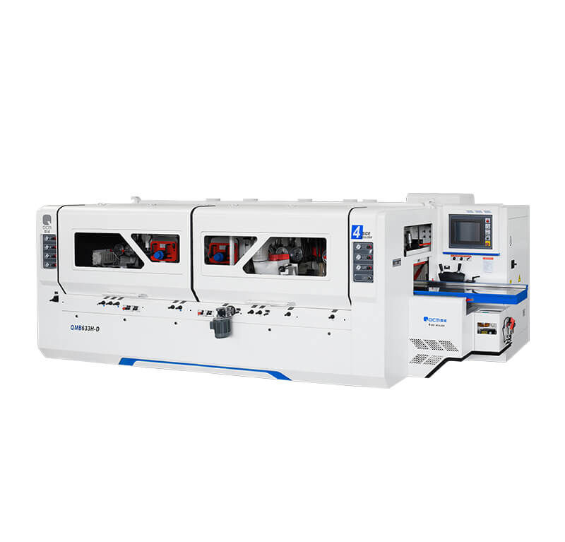
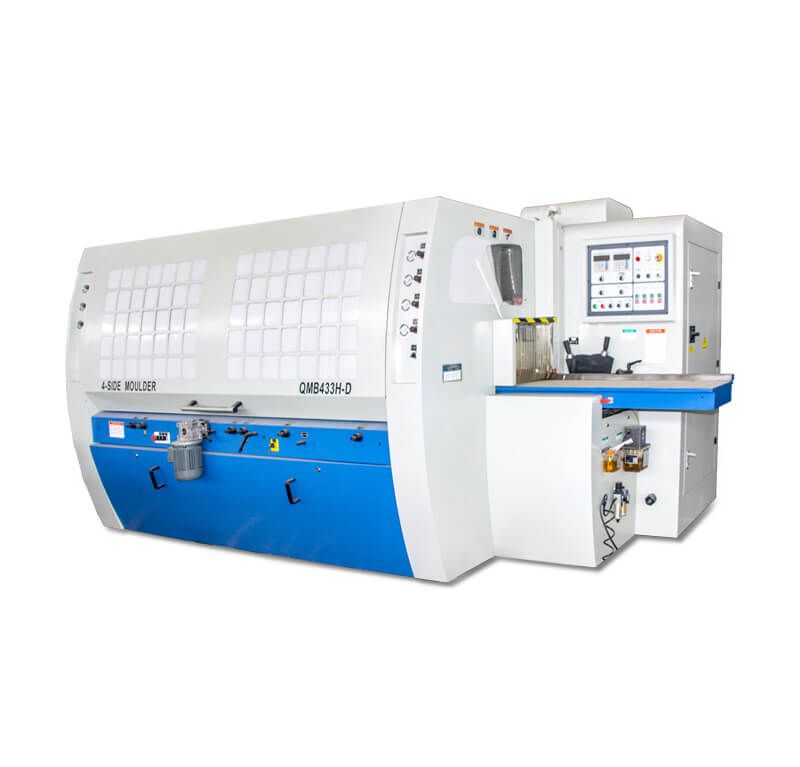
4 SIDE PLANER MOULDER
We have our own casting workshop, so we can ensure our 4 side planer moulder machines with whole piece casting machine body for a stable performance.
The spindle of four side moulder is precisely machined, dynamically balanced, and precisely assembled, so it runs smoothly and has high accuracy;
Siemens and Schneider electrical products and appliances insure four side moulder run well with a stable performance.
Get a FREE consultation!
featured moulder Four sided planer woodworking machine
Woodworking 4 SIDEd PLANER MOULDER MACHINE
Name:
Category:
Application:
After-sales:
Advantages:
4 Sided planer moulder machine
Woodworking machinery
Wood furniture factory, woodworking sawmill
Video technical support, Online support
Casting
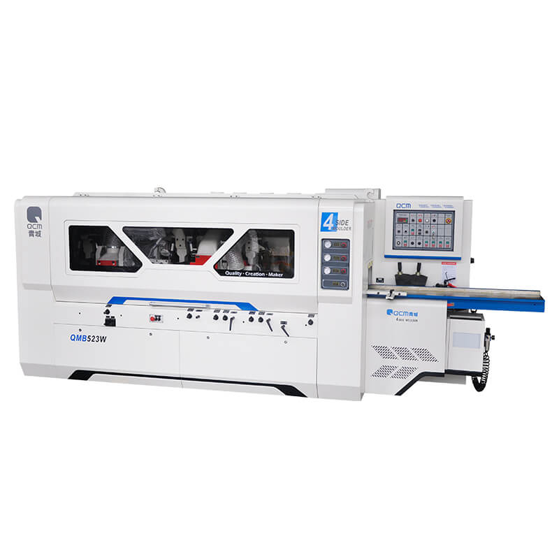
Table of Contents
Four sided Planer moulder Machine Manufacturer
Advanced technological solutions for 4 sided wood planer moulder machine to produce wooden flooring; heavy duty wood planing machine for beam or wooden house; four side planer for window elements, four side planer for doors; four sided planer for stairs; 4 sided planer for frames; four side moulder for wood moulds for furniture, wood planer moulder machine for wooden furniture, and universal spindle four side planer for garden furniture that guarantee flexibility and productivity for small and large production batches.
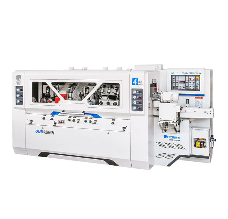
33H series heavy-duty and 23GH series 4 side planer moulder has strong spindles with 50mm diameter. If you are looking for a high productivity, high precision, and labor cost-cutting 4 side planer moulder, our GH series is right for you.
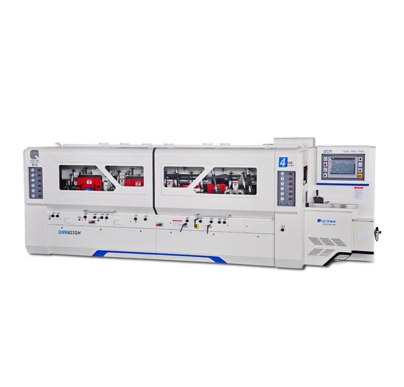
We have spent great efforts in analyzing the high speed machining technology for our 4 side planer moulder, and successfully presented a new generation high speed planer moulder. Our QMB623GH, QMB723GH, QMB823GH are highly popular models. Our four side moulder has excellent powerful feeding performance which is achieved through a gearbox transmission. Extra powerful motor drive combined with frequency inverted control feature maximum smoothness in heavy duty machining.
Furthermore, the second top and bottom, two vertical cutters of QMB623GH, QMB723GH, QMB823GH 4-side moulder are equipped with Automatic sharpening mechanism. In today’s competitive environment, our 4-side moulder is designed and engineered to help you create more profits with less labor cost.
How to select a successful 4 sided planer moulder Machine (for your customer, or for your own factory)?
You can select the model of 4 sided planer moulder based on your material size. 4-sided planer moulder models are available for different max. working width:
| Working width | Model No. |
|---|---|
| 120mm | QMB4012D-T, QMB4012D-GH, QMB4012GH, QMB4012E-GH, QMB412D-T |
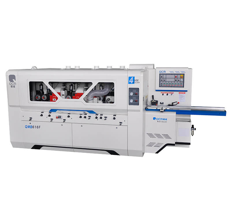
| 160mm | QMB4016C-T, QMB4016CM, QMB516E-T QMB4016S-T, QMB516S-T, QMB4016F-T, QMB616F-T. |
| 180mm | QMB4018A-T, QMB4018A-GH, QMB4018GH, QMB4018D-GH, QMB4018E-GH, QMB418E-T, QMB418E-GH. |
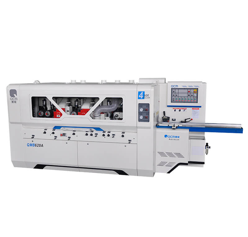
| 200mm | QMB4020G, QMB420G, QMB6020G, QMB4020C-T, QMB4020CM, QMB520AT, QMB520GH, QMB620GH, QMB4020F-T, QMB620A-T, QMB620RL, QMB720W(6+1) |
| 230mm | QMB523A, QMB623A, QMB623A-K, QMB523W (4+1), QMB623W(5+1), QMB723W(6+1), QMB623R, QMB723R, QMB623GH, QMB723GH, QMB823GH |
| 330mm | QMB633H-D |
A Wide Range of Spindle Configurations for our 4 sided planer moulder.
- Normally, if you only need the basic function of 4 sides planing, then 4 sided planer moulder with 4 spindles (heads) will be economic choice.
- If you want to get a better processing effect, 5 and 6 spindles are recommended.
- If you need to process for click system, or other complicated structure or profile, 720W will be perfect solution.
- If you process the big size pine timber, 7 or 8 spindles four side moulder will be perfect solution.
- More spindles for 4 sided planer, means better the processing effect will be.
The variable feeding speed is available.
●A series means basic four sided planer moulder, economic one, while the function is also very basic.
●AT series means upgraded function with frequency compared to A series 4 side wood planer .
●A-K means upgrade function with touch screen and memory system.
●GH series means high speed, can be adjusted from 10-60 m/min. Including QMB623GH, QMB723GH, QMB823GH, QMB520GH. Other models of 4 sided planer moulder can be adjusted from 8-36 m/min.
Safety enclosure of 4 sided planer moulder is for safety of operators. And if safety enclosure is not so important for you, you can select those models without enclosure, which is economic type to save your purchasing budget.
How to change cutters for four side moulder?
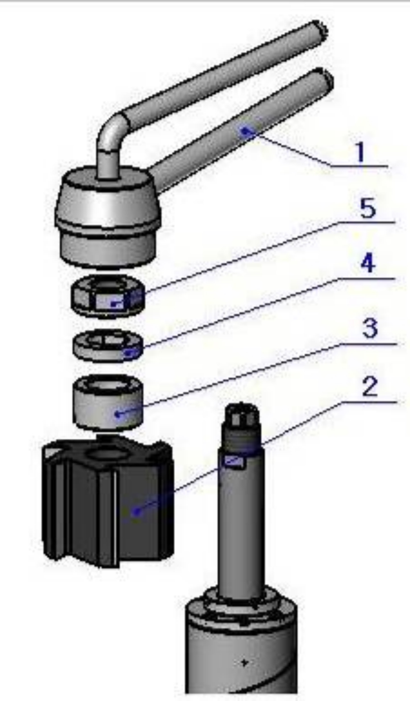
Installation of planing tools of four side moulder
Determine the quantity and thickness of ring 3.
Clean the mating surface of tool and spindle. Apply oil to the rings, safety rings and spindle nuts to prevent them from corrosion.
Install the tool 2, ring 3, safety ring 4 and spindle nut 5 in turn. Tighten the spindle nut 5 by special combination wrench 1 and make sure it could not loosen by itself.
Rotate the spindle by hand and make sure it runs freely.
To dismount the tool, the above procedures shall be performed in inverted sequence.
Note: The safety ring must fit into the slot of the spindle for at least 3 mm, so that the tool could be tightened axially and will not be over distorted.
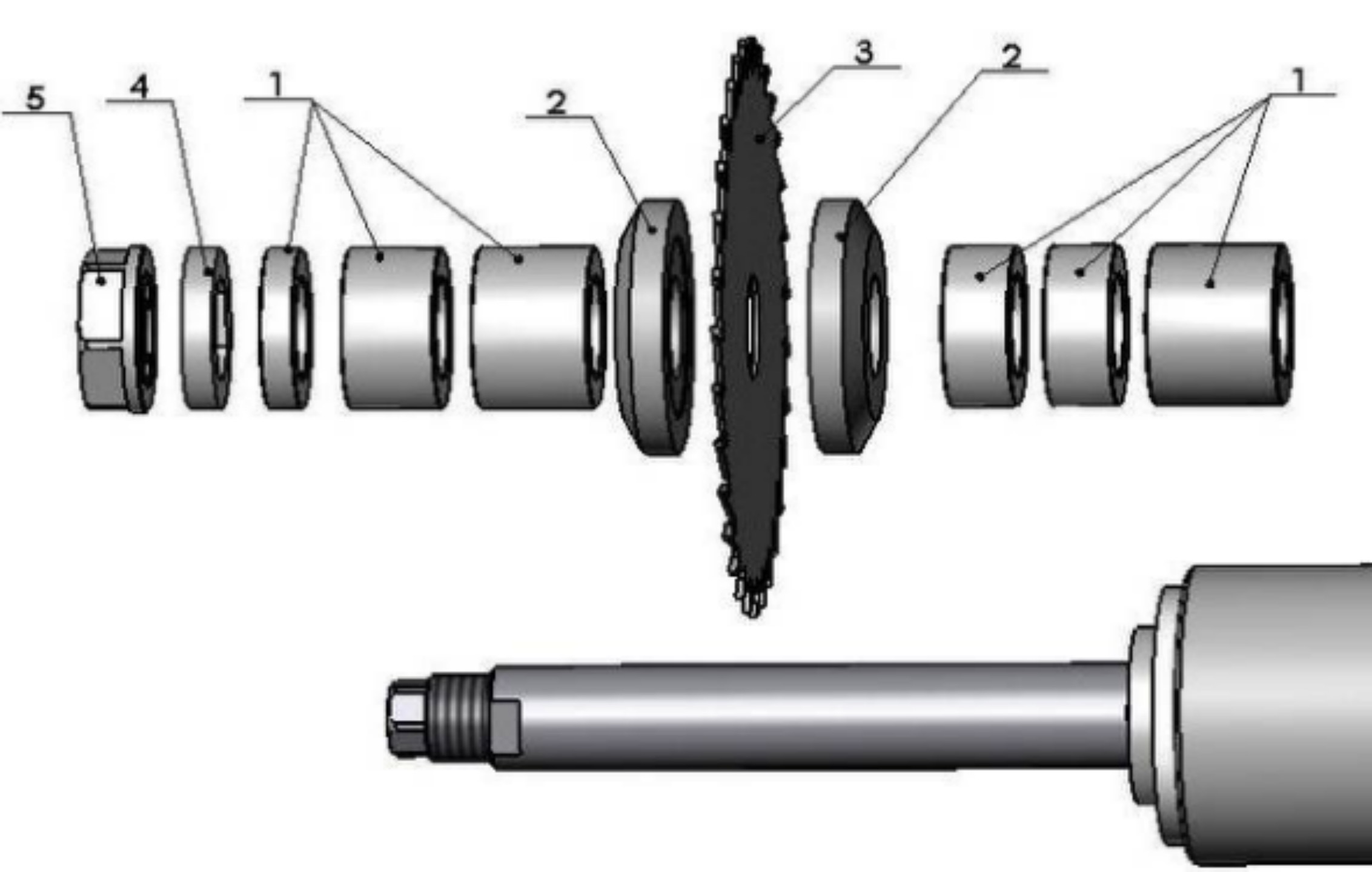
Determine the rough clearance between the blade and the spindle shoulder according to the working requirements. And determine the quantity and thickness of rings 1 between the blade and the spindle shoulder and rings 1 at the outside of the blade. Clean the mating surface of tools and spindles. Apply oil to the rings, safety rings and spindle nuts. Install the rings 1 between the blade and spindle shoulder, clamping plate 2, blade 3, clamping plate 2, rings 1 at the outside of the blade, safety ring 4 and spindle nut 5 in turn. Tighten the spindle nut 5 by the special combination wrench and make sure it could not loosen by itself. Rotate the spindle by hand and make sure it runs freely. Perform further precise positioning by the axial adjustment device of the spindle while adjusting the spindle. Note: Make sure the teeth of the blade are in correction direction. While applying saw blades, operators must strictly follow the safety precautions to add safety devices.
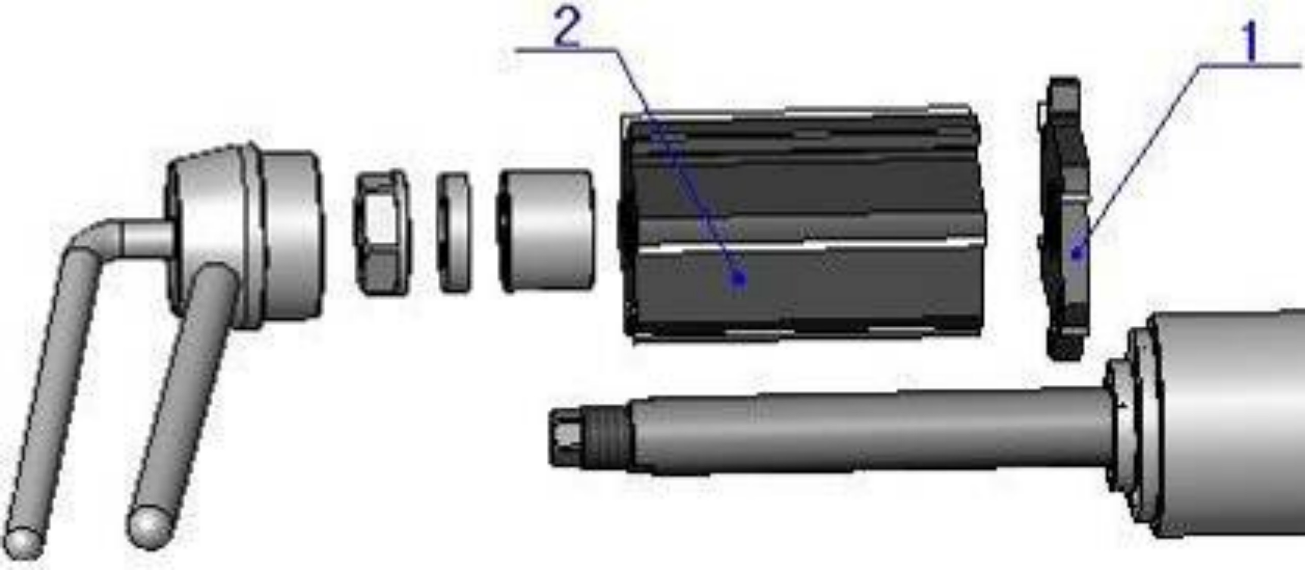
The slotting cutter1 is installed on the first bottom spindle for producing a reference plane from the bottom on the right side of the work piece. It is tightened by the planing cutter 2 in the axial direction. The installation steps: install the slotting cutter, planing cutter, ring, safety ring and spindle nut in turn, and tighten the spindle nut with the special combination wrench, so that it does not loosen by itself. Then turn the spindle by hand and make sure it runs freely.
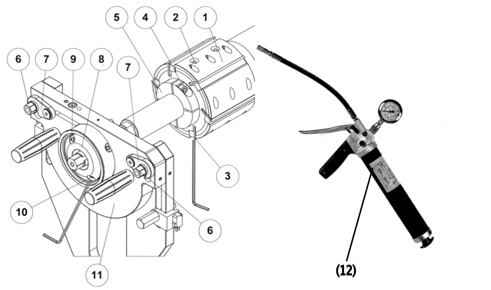
Hydraulic tools could greatly improve the stability of the tool spindle running, ensuring the better machined wood surface.
It is recommended that the L/R vertical spindles, rear top spindle, second and third bottom spindles should use hydraulic cutters. And this machine all the horizontal spindles are equipped with outer bearing supports.
Note: when install the cutter, must first remove the outer bearing support device.
4.1 Dismounting of hydraulic tools
1. Loosen the pressure relief screw (10) on the outer bearing (8) until oil spills out, then retighten.
2. Loosen the two nuts (6), unlock the two pressing plates (7), then pull out the bearing seat plate through the handles on the plate (11) with both hands.
3. Loosen the hexangular screw (4) on the safety ring (5), then unscrew and remove the safety ring (pay attention to the installation position of the safety ring).
4. Loosen the pressure relief screw (3) on the hydraulic cutter (1) until oil spills out and then retighten.
5. Use the tool holder to remove the tool.
4.2 Installation of hydraulic tools
1. Install the cutter(1) on the spindle and push it to the spindle shoulder.
2. Turn the safety ring(5) into place, and insert into the pin to prevent the cutter from rotating; and keep a small gap between the cutter and the safety ring.
3. Tighten the tightening screw(4) on the safety ring.
4. Insert and secure the pressure nozzle (2) on the cutter with the high pressure oil gun (12), to apply a pressure of 300bar to the cutter. After it, release the pressure of the oil gun and remove the oil gun.
Note: The hydraulic outer bearing support unit shall maintain the pressure above 200bar in process of working. And fill the pressure in time when the hydraulic pressure is reduced.
4.3 Installation of outer bearing support unit
1. Install the outer bearing support plate(11) and lock the two pressing plates(7), then tighten the two nuts(6).
2. When the cutter spindle moves backward to the limit position along the axial direction, also the outer bearing (8) is pushed toward cutter spindle to the appropriate position, so that the entire axial travel range of the cutter spindle can be utilized.
3. Insert and secure the pressure nozzle (9) on the outer bearing(8) with the high pressure oil gun (12), to apply a pressure of 300bar to the outer bearing. After it, release the pressure of the oil gun and remove the oil gun.
Use the same method to install the hydraulic cutters on the left and right vertical spindles, but the vertical cutter spindles do not have outer bearing support.
Note: the outer bearing must be able to slide freely in the axial direction when the cutter spindle moves in the axial direction. When the outer bearing is hydraulically locked, the cutter spindle cannot be moved in axial direction again.
Note: The hydraulic cutter must be tightened by applying a pressure of 300bar to the hydraulic sleeve inside the cutter. It is not allowed to tighten the cutter through the safety ring.
5. Adjustment
After being familiar with the control system, operation method and cutter installation method of the machine, the machine can be further adjusted and do commissioning. First, open the main cover of the machine and set the operation mode to “Hand” mode on the HMI. (see operation manual)
Note: For safety, the incoming power of the machine must be turned off before assembling or disassembling the cutter tool.
5.1 Baisc Adjustment
5.1.1 Counter(position indicator) Correction
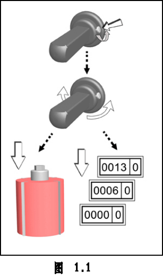
After you install, change the tool or adjust the cutting spindle, need to re-check the display value of the counter.
Adjustment methods as below:
1. Loosen the screw of the adjusting ring.
2. Turn the adjusting ring to make the number meet the required value.
3. Then tighten the screw again.
Note: the final turning direction of the adjusting ring must be the same as that of the adjusting rod of the cutter spindle.
5.1.2 Basic Adjustment Of Cutter Spindle
All spindles of 4 sided planer moulder can be moved up and down, forward and backward. When adjust, first release the locking handle corresponding to the adjusting direction, and then adjust. After the adjustment is in place, re-tighten the locking handle.
In order to clear the gap of the cutter spindle, no matter adjust the cutter spindle to move up and down, or to move back and forth, the final turning direction of the adjusting rod of the cutter spindle should be that making the cutter spindle is close to the workpiece.
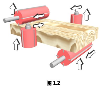
Why choose us as four sider moulder supplier?
We are the only woodworking manufacturer who has its own casting workshop, and the most advanced CNC machining center. Those advantages ensure us to provide biggest support to our distributors with fast delivery.
Normally, if you use regular voltage as ours 380v 50hz 3 phase, we will have ready stock for popular models of 4 sided planer moulder , or it will take 2 month for new production;
If you need customized voltage such as 440v 60hz, or other type, it will take 3 months for production because of customized motors.
As the leader of woodworking machinery manufacturer in China, Smart Panther has the strongest technology research and development capabilities, advantage equipment, excellent processing technology, 50+ years of manufacturing experience and strict quality control management.

Casting Workshop
Five tons of inverter electric furnace is pouring molten iron

Machine Molding
One shot of casting workshop, it's making machine molding.

Machine Molding
One shot of casting workshop, it's making machine molding.

Casting Machine Body
Casting machine body is processed in OKUMA five side gantry machining center.

Three-coordinate Measuring
Mitutoyo three-coordinate measuring machine is testing machine parts

FMS Tool Magazine
FMS flexible production line has 70 working stations with thousands of tools.

Okuma Five-sided Gantry
Okuma five-sided gantry machining center is processing machine body.

OKK Machining Center
Japanese top brand OKK large machining center is processing.

Flexible Production Line
Mazak FMS flexible horizontal processing center is working.
Main features of our four sided planer moulder
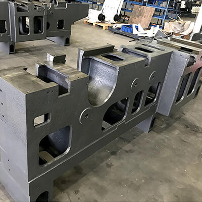
casting machine body
4 sided planer has extra heavy one-piece casting iron machine body. It’s specially heat treated for maximum stability and rigidity by standard configuration.
SIEMENS ELECTRICAL
Our 4 sided planer moulder use Siemens and Schneider electrical products and appliances insure the whole machine run well with a suitable performance

airtac cylinder
Pneumatic pressure of the feed rollers can be easily setted to provide an outstanding feeding effect for our 4 sided moulder.
SAFETY ENCLOSURE
The full heavy gauge steel sound insulated safety enclosure serves as a chip guard and helps 4 sided planer moulder to reduce noise and has strobe free lighting.
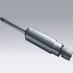
high precision
All spindles are precision constructed and specially heat treated to provide 4 sided moulder maximum cutting stability and permanent accuracy.
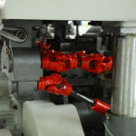
heavy duty gearbox
The feed rollers of 4 sided planer are driven through a combination of extra heavy universal shafts and gearbox, ensure no loss of power transmission. A smooth feeding effect is assured.
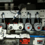
outstanding feeding
Our 4 sided planer moulder has more top and bottom powered rollers than most competitor’s four side moulder. And this is an important reason for outstanding feeding performance.

heard-chromed
The entire cast iron chromed in-feed table is heat treated for maximum stability. In-feed table & fence adjustment of 4 sided moulder is quickly accomplished by means of a quick-setting levers.


